Foundry & industrial processing Machinery EQUIPMENT & SYSTEMS
U.S. & Canada Call 1.800.457.5456
Basics of Sand Mixing
Home Articles Basics of Sand Mixing
Simple Solutions That Work!™, Volume 1, Sept. 2014
Written - Jack Palmer
Jack Palmer
President
Palmer Manufacturing & Supply, Inc.
Ken Strausbaugh
Technical & Testing Manager
Palmer Manufacturing & Supply, Inc.
Article Takeaways:
Mixing of any material or combination of materials is accomplished by moving the materials together against themselves. The mixer, regardless of design or materials to be blended, exists only to accomplish a uniform dis-tribution of the components. Whether mixing concrete, polymers, liquids, powders, or silica sand with differing chemical system, the purpose of the mixing machine is to move the materials against themselves.
In our industry we are mixing sands with very small amounts of different binding agents, all having different and variable properties. The first sand that exits the chamber is obviously not the same as the sand a few seconds behind it as there is really nothing for the first sand to move against. Even with today’s technologies (timers, flowmeters, valve systems), we cannot get away from this basic premise; will the first sand be usable and will it be exactly the same as the sand right behind it.
It is a simple process to catch the first 1-2 seconds of sand that exits the mixer and then put it in the molds as soon as the pattern is covered. A properly trained and motivated mixer operator will waste very little sand.
The object of the continuous mixer is to produce a quality core or mold using just enough binder to obtain the desired casting results at the lowest possible cost. Chemicals are a high percentage of the casting cost. Lower resin levels reduce costs, improve the reclamation process, and improve the working environment.
Sand Temperature
It is important to control the temperature In order to keep chemicals levels as low as possible. The preferred temperature for the sand and resin mixture is in the 85-95oF range. The set time of the PUNB system is either doubled or halved for every 18oF change in sand temperature. Unless sand temperature is well controlled, production rates will suffer. Even if the strip time is reduced with additional catalyst (expensive) the evaporation of solvents remains retarded due to the low sand temperature resulting in a higher potential for gas defects.
Heating sand with a traditional fluidized resistance element design can be costly because compressed air is cool and therefore uses a lot of power to raise the sand temperature 20-30oF at the flow rates required.
This high kW requirement can add to the monthly electric bill if it is a demand-based system. While the end temperature is important, the consistency and repeatability of temperature is equally important. The capital and operating costs of correctly sized sand heaters are high, but can usually be easily justified by lowered resin requirements, greater production levels, fewer scrap molds/cores, and more consistent production.
Resin Temperature
Resin temperature control is important for consistent metering and for optimum mixing. Some chemicals experience a significant increase in viscosity as the tem-perature is decreased. This increased viscosity may slow the speed of motors driving positive displacement pumps reducing the flow of that chemical. Higher viscosity resins introduced into a mixing chamber that processes sand for 1-3 seconds may not be sufficient to uniformly distribute the chemical over the mass of sand.
The normal response to cold resins is to install a drum heater or heat lamps. While these are helpful, they can be problematic; if left on too long or at too high a temperature, the characteristics of the resin can be dramatically changed. The relatively slow heat transfer rates of static chemical in a drum or tote prevents uniform heating of the entire contents. The outside couple inches of chemical can be overheated while the inside remains at the original ambient temperature. High temperature of portions of the fluid can cause solvent evaporation or resin advancement. The performance, viscosity, and metering characteristics of the chemicals may all change and vary with this method of temperature control.
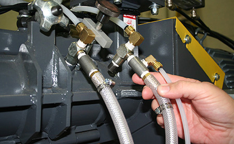
Air assisted jet assembly removed from the mixing chamber for physical calibration.
An improved method of temperature control uses a dedicated recirculation pump that takes the chemical from the bottom of the container, runs it through an in-line heating device, and returns it to the top of the container. This system keeps all chemical throughout the container at the same temperature at all times. Additions to this container should never be more than 25% of the container size to allow the heating system to recover as quickly as possible while still in production.
The distribution lines to the mixer should include diverter valves located as close to the mixer inlet ports as practical in order to maintain the resin temperature all the way to the mixer.
Mixer Design
A properly designed high speed continuous sand mixer requires a number of criteria to be met. While a mixer is a very simple mechanism in itself, a great deal of technology is required for optimum results.
Mixing efficiency depends on retention time, blade tip speed, thickness of the sand on the inside of the chamber, and horsepower.
Retention time
If the mixture is in the chamber for too short of a time, there is the potential for weak molds/cores, streaking, resin balls, etc as a result of inadequate dispersion of the chemicals. If the residence time is too long, there is the possibility of exceeding the work time of the mix and/or heating of the sand. Either can cause a breakdown of the sand resulting in low strength cores or molds. Each application differs relative to sand type, shape, screen analysis, sand dry additives, and chemical physical properties. Higher retention times can result in a post flow of small amounts of sand. Proper testing of a particular application is required to optimize the reten-tion time.Blade tip speed
Retention time is controlled by blade angle and rpm (blade tip speed). Careful testing along with proven historical results determines this design. Some systems perform better with a low speed/long retention time while for others, the opposite can be true.Varied combinations of three different blade angles; 45o forward, 0o, and 45o reverse can properly blend virtually any sand in a continuous mixer.Variable pitch threaded blades should be avoided as they loosen, take much longer to install, and provide an opportunity for misadjustment.
Satisfactory centrifugal mixing is usually achieved at tip speeds between 1,250 and 2,500 ft/minute in a mixer of practical length. At this speed, the sand/resin mixture is being actively rubbed against itself in a peripheral layer along the wall of the mixing chamber.
Thickness of the sand on the inside of the chamber
There is a minimum and maximum amount of sand that can be efficiently mixed with a given size of mixer. Too little sand and there isn’t enough mass to blend together. Too much sand and the sand on the inner portion of the sand wall is not rubbing together with the same velocity.Horsepower
Sufficient horsepower must be available to keep the shaft speed consistent. While standard motor rpms 890, 1150, and 1750 can be used in many cases, VFDs (variable frequency drives ) can be used to achieve the optimum speed for a given combination of throughput, resin system, and sand (size, shape, screen analysis). Usually gearboxes and pully/belt designs should be avoided as they are an unnecessary and uneconomical mechanical complication.
Metering of Materials
Accuracy and repeatability of material addition is critical. The free flow of sand itself is critical to assure a consistent sand flow for the no bake process. Water is the kiss of death – as little as 0.2% moisture on the sand will mas-sively alter the sand flow rates. Chemical performance will also be inhibited.
Sand by nature does not lend itself to precision meter-ing in comparison to the levels achievable with liquids. A fixed orifice metering system for sand is optimal. If a slide gate is used, it should be a hole, not a plate that hits an adjustable stop. The fixed orifice allows for a smooth and repeatable flow of sand into the chamber. Articulated mixers with a “dam gate” metering design should have a rigid support under the belt to keep the relationship between the bottom of the dam and the top of the belt as consistent as possible.
The fine powders that are sometimes required for metallurgical or surface finish need uniform dispersion. These powders are usually very difficult to meter as they have a tendency to rathole and pack. There are some that will actually achieve a negative angle of repose.
The best current technology for metering small precise amounts of these powders is a flexible hopper wall, centerless helix design. The urethane hopper is externally “massaged” which keeps the powder active and of a consistent density around the centerless helix. The centerless helix is used in place of a traditional auger or screw since it will not “pack up” with material. By maintaining a consistent density of material, and very precisely controlling the rpm of the helix, very accurate amounts of difficult powders can be metered. It is critical that the helix turns at least 45 rpm and no faster than 200 rpm. Any screw type handling device discharges in a pulsing type flow because every flight pushes a given amount out of the housing. By turning at least 45 rpm this pulse is minimized. Lower speeds will produce the right amount of powder per minute, the correct amount per second is necessary. This is critical because the retention time of sand in a modern high speed mixer is usually only 2-5 seconds. Helix speeds above 200 rpm do not provide enough time for the material to react between the flights resulting in inaccurate and non-re-peatable flows. The helix speed is kept in the correct range by selecting the correct diameter of the helix.
There is a multitude of liquid metering equipment available for foundry chemicals. Material compatibility must be established first and then the accuracy, repeatability, and durability of resin metering systems must be considered. The three main criteria determining the equipment required for a given application are: output range, chemical density, and viscosity.
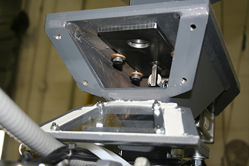
Orifice-based slide gate metering device (window guard removed for photo)
While it is important to maintain an accurate resin flow, an accuracy of less than plus or minus 1% of total flow isn’t always necessary. While accuracies of 1/10 percent are certainly achievable with today’s Coriolis flow meters, they may not always be justified because of the cost.
A close tolerance gear pump coupled with a properly designed drive system will result in consistent, repeatable delivery. There is no such thing as a positive displace-ment gear pump. There are fit tolerances in any gear style pump that must be maintained in order to allow the parts to move against each other. This is normally called slip – which is the amount of liquid that can bypass or slip past the gears. It is usually minimal, but is a consideration as lower cost pumps traditionally have more slip because it is less costly to manufacture to looser tolerances. Pump slip which, as a function of speed, is increased at lower speeds must be considered in the pump sizing design phase.
A pump turning at too high of a speed can result in cavitation and premature wear. Pump construction, size, and speed of rotation are very different depending on the liquid, flow rate, and viscosity.
Equally important in the pumping system is the drive. Maintaining an exact rpm is critical but maintaining the correct rotating speed per second is even more critical. If a system is designed with the wrong pump or drive for a given resin system, there is a very real possibility of a one minute calibration test showing repeatable flow but still having significant flow variation per second. DC motors with speed controls and AC VFD controlled motors are both proven to provide repeatable variable speed over a large speed range. PLC’s with feedback from tachometers or flow monitoring devices can be used to control flow rates by adjusting the speeds of the motors.
Tachometers only measure the rpm’s of the motor or pump while fluid monitoring devices actually measure the fluid flow rate. There are a number of fluid monitor-ing devices but the most commonly used are volumetric, (dual gear), mass flow (Coriolis), or magnetic (electrical conductivity). The outputs from all of these devices are then used to adjust the motor speed to achieve the de-sired speed or flow.
It is critical with any system to physically measure/verify chemical flows at the mixing chamber. Many times we see people relying on a rpm or display setting or checking flow using a 3-way valve right after the pump to assure correct flow. While these may be correct at most times, measuring at the mixing chamber is always correct. The fitting that goes into the chamber should be removed.Even if the hose going to the fitting is removed there is a very real possibility of the fitting being restricted in some way even if a system is equipped with purge air. A physical measurement should be regularly used to verify the accuracy of the flow even with installed meters occasionally.
The flow control system should always be equipped with a calibration timer to ensure the calibration cycle, (commonly 30 seconds) is always the same. There is a large percentage variation between 28 and 32 seconds which is common when calibrating by hand with a watch.
A high quality scale that is regularly calibrated is an important part of control. It needs to be durable enough to stand up to the foundry environment and accurate enough to assure measurement within the acceptable tolerance of the process.
For such a simple mixing machine, there can be a myriad of potential problems. Usually these problems are associated with improper maintenance or cleaning. Performing regular maintenance, calibration, and clean-ing are critical to the production of quality molds and cores. It is much better to catch problems in the molding area or core room. The alternative is to discover mold/core related defects in the cleaning room or, worse, in the machine shop, or worse yet, as rejections from the customer. The amount of time spent maintaining and cal-ibrating the mixer is infinitesimally small in comparison to the costs of neglecting to do this routinely.
- far, the majority of service calls we receive turn out to be simple plumbing issues. A properly designed pumping system with the supply above the pump (which provides a flooded suction), with the pump as the lowest point in the system, and the inlet to the mixer above the pump, but below the supply will produce accurate and repeat-able performance. Regular replacement of hoses, fittings and piping will pay off many times in the long term.
It is not uncommon for hours or even days of production to be lost simply because of an internally collapsing hose, floating obstruction in piping, improperly rerouted hoses and the like.
Probably the most critical item in day-to-day reliability and consistency of production is the cleaning of the mixing chamber. It is only necessary to regularly clean the mixing blades, shaft, and discharge from the cham-ber. Cleaning should be performed every shift or day. It only takes a few minutes to clean a chamber on a regular basis. Whether by the shift, by the day, or by a certain number of operational hours, cleaning needs to be performed on a regular basis.
It is also important to never clean the inside of the mixing chamber unless replacing blades. There should be minimal clearance between the edge of the blade and the inside of the mixing chamber to assure all sand is mixed. As a blade wears, the lining is regenerated which maintains the minimum distance between the end of the blade and the inside of the mixing chamber.
The high speed continuous mixer is a critical component in the casting production process, and as such deserves and requires rigorous attention to detail.
Palmer Manufacturing & Supply, Inc.
18 Bechtle Avenue Springfield, Ohio 45504
US/Canada: 800.457.5456
Phone: 937.323.6339
Fax: 937.323.2709
Sales E-mail: [email protected]
Palmer companies
Palmer Manufacturing & Supply, Inc.
Palmer Engineered Products, Inc.
Klein Palmer, Inc.


Copyright © 2024 Palmer Manufacturing & Supply, Inc. | Terms and Conditions | Privacy Policy
Web published by Marketing Options, LLC.